in4mo Floor Planner
Här visar vi hur man använder in4mo FloorPlanner-verktyget i mobilappen in4mo Task Reporter för att skapa planritningar.
Översikt
in4mo FloorPlanner är ett ritverktyg för att skissa våningsplan och används parallellt med det tidigare ritverktyget. in4mo FloorPlanner är en funktion som finns tillgänglig i besiktningsrapporter och är därför endast tillgänglig på surfplattor samt i Windows-appen, som även kan användas på PC.
Genom att använda FloorPlanner blir illustrationerna av våningsplanen mer exakta och tydligare presenterade. Ritningarna görs skalenligt och mått kan även användas i in4mo Kostnadskalkyl (iCC). Möjligheten att lägga till fönster och dörrar möjliggör automatiska beräkningar av både total väggyta och faktisk yta.
Här går vi igenom de olika funktionerna i in4mo FloorPlanner. Detta är en genomgång av funktionaliteten och inte ett fristående exempel på hur ett korrekt våningsplan ska se ut. Skärmbilderna i guiden är tagna på en Windows-enhet, men verktyget fungerar på samma sätt på Android- och iOS-enheter (Apple), även om färger i vissa fall kan skilja sig något.
Så använder man FloorPlanner
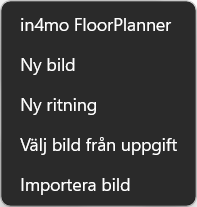
För att använda FloorPlanner måste man först öppna en rapport och därefter scrolla till antingen avsnittet ”Våningsplan” i rapporten eller till ”Bilagor” längst ned. Klicka på det tomma fältet och välj sedan ”in4mo FloorPlanner”.
När du klickar på in4mo FloorPlanner öppnas följande fönster.
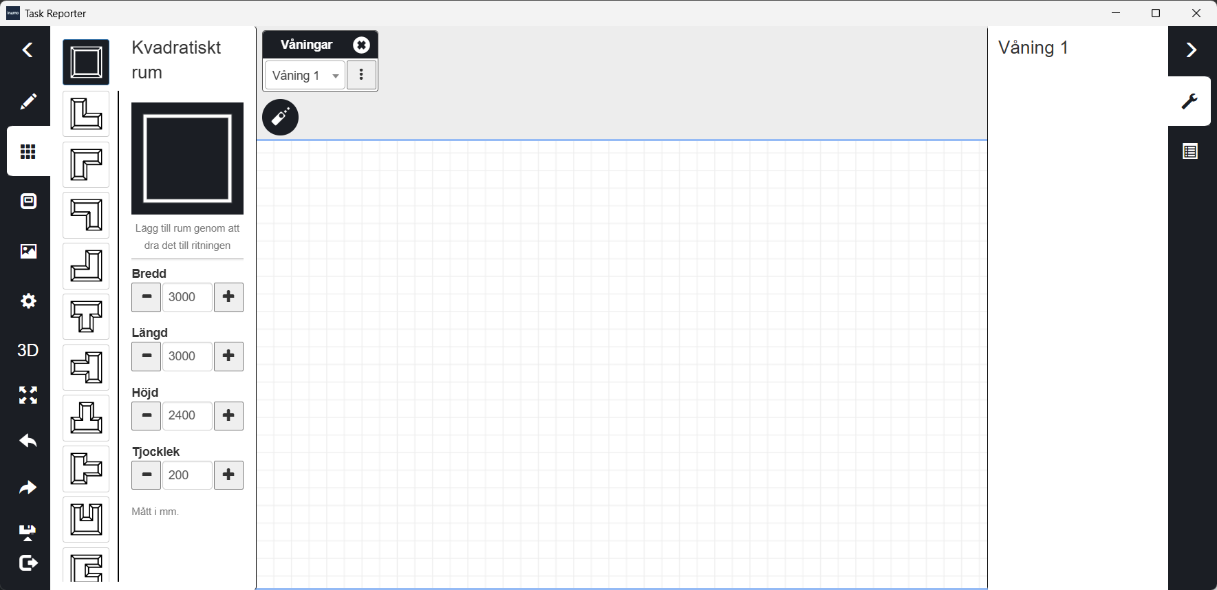
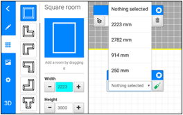
Det finns flera fördefinierade rumstyper i standardvyn under den tredje ikonen. Först, bör man välja det rum man vill använda genom att klicka på det. Rummets mått kan ändras innan man lägger till det i våningsplanen.
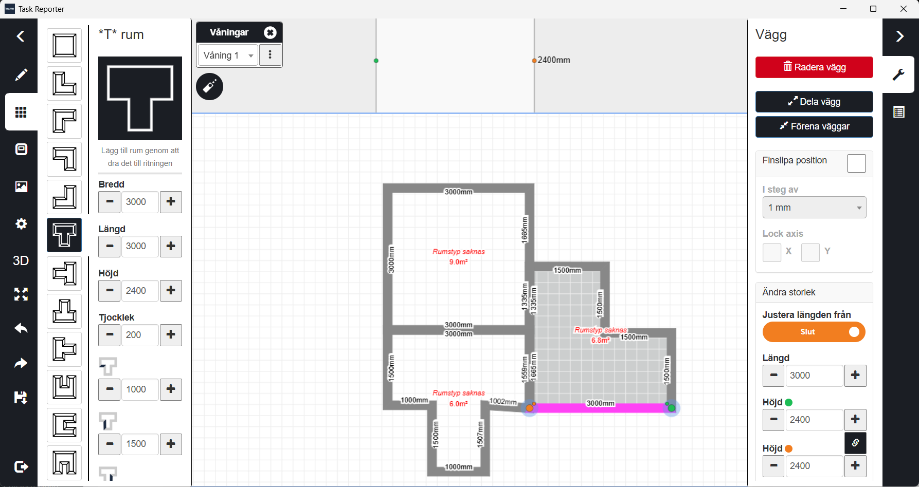
Rummet läggs till genom att dra det till det vita området i våningsplanen. Man kan ändra rummets dimensioner när som helst genom att markera en vägg och dra den, eller genom att ändra måtten i panelen till höger. Dimensioner kan även ändras med hjälp av en Bluetooth-ansluten mätutrustning, vilket beskrivs mer i detalj senare.
När man markerar en vägg får man även möjlighet att ta bort den.
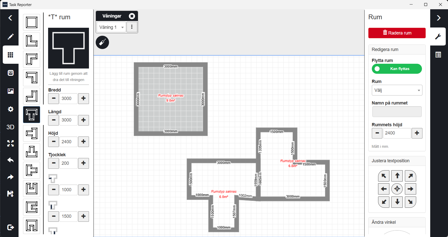
Om man önskar ta bort ett helt rum markerar man rummet och väljer Ta bort rum i menyn till höger.
Ett rum kan även flyttas till en annan plats vid behov. För att göra detta måste rummet först markeras och därefter låsas upp genom att välja Olåst under Rum (Rumsflytt) i menyn till höger. En liten hänglåsikon i rummet visar om rummet är låst och inte kan flyttas. När ett rum låses, låses även angränsande rum automatiskt. Här kan man även justera rummets höjd genom att markera rummet och ändra inställningen i menyn till höger.
I ärenden där in4mo Kostnadskalkyl (iCC) används visas texten ”Rumstyp saknas” i varje rum, som visas i bilden nedan. Så länge denna text visas i ett eller flera rum går det inte att spara våningsplanen förrän alla rum har fått en rumstyp.
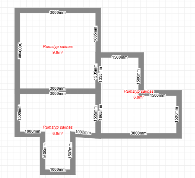
Detta innebär att en rumstyp måste definieras för att rummets mått ska kunna användas i iCC. Rumstypen anges genom att markera rummet och välja en rumstyp i rullistan Rumstyp till höger. Om samma rumstyp ska användas i flera rum (t.ex. flera toaletter) bör de övriga rummen namnges.
Observera att ändringar av rummets dimensioner tar bort rumstypen. Därför rekommenderas att rumstyper anges först efter att rummens form och mått har fastställts, annars måste rumstyperna anges på nytt.
När rummen har skapats har du grundstrukturen för våningsplanen. Därefter kan du börja lägga till extra väggar vid behov, måttlinjer, markera skador, namnge rum, lägga till hushållsapparater, dörrar, fönster och andra ikoner.
I det här exemplet börjar vi uppifrån.

Genom att klicka på denna ikon döljs menyn till vänster så att man kan granska våningsplanen mer detaljerat. Genom att klicka på pilen igen, visas menyn.

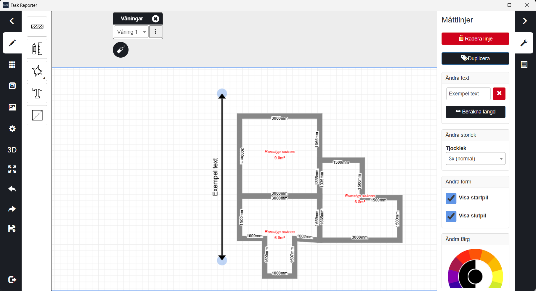
Med den andra ikonen kan man rita väggar, lägga till mått, markera skador och skriva text.

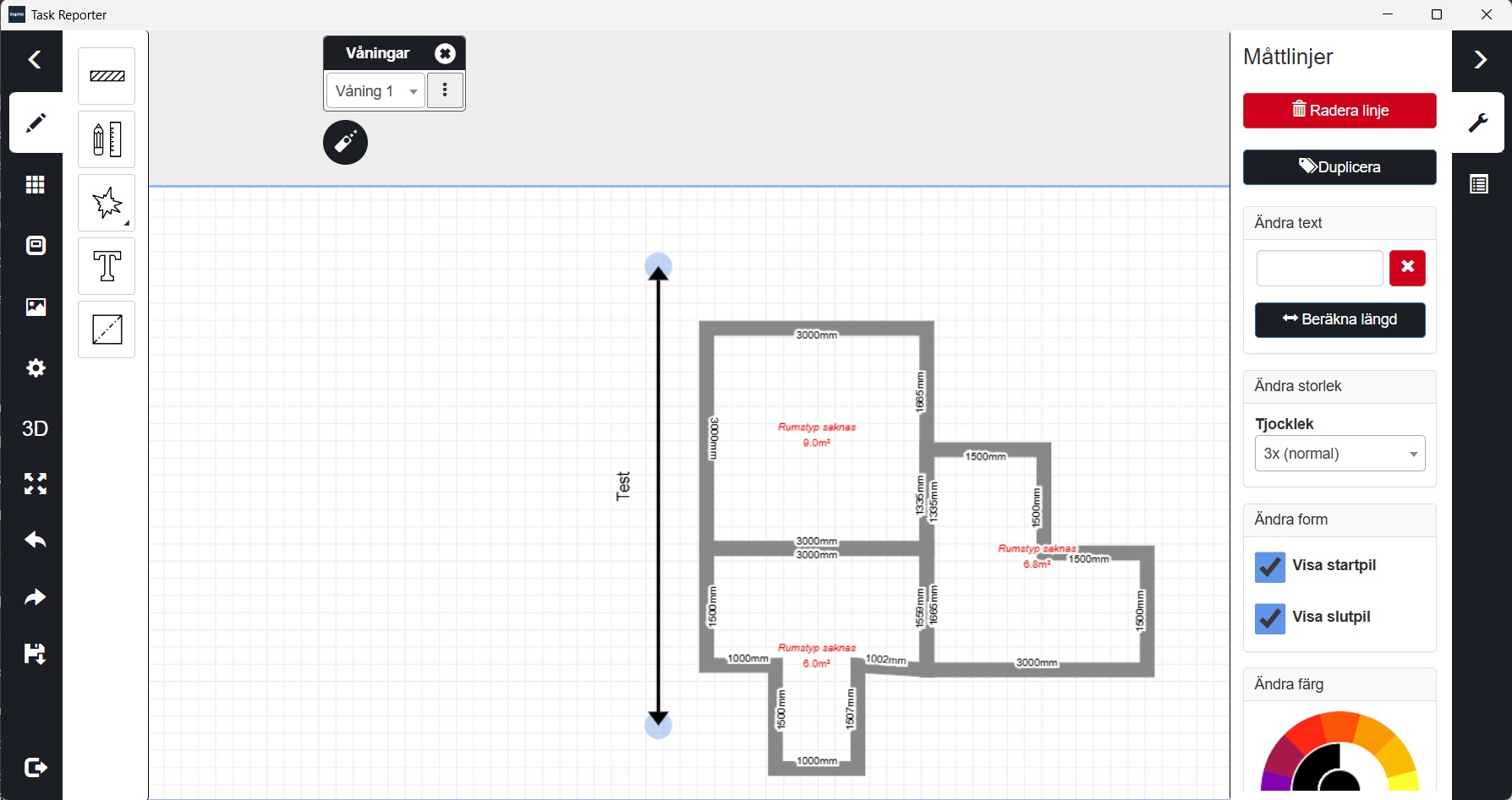
Den andra ikonen ger möjligheten att rita pilar med eller utan text. Pilarens storlek, färg och stil kan justeras efter egna behov. Genom att trycka på Beräkna längd ersätts texten med linjens längd.
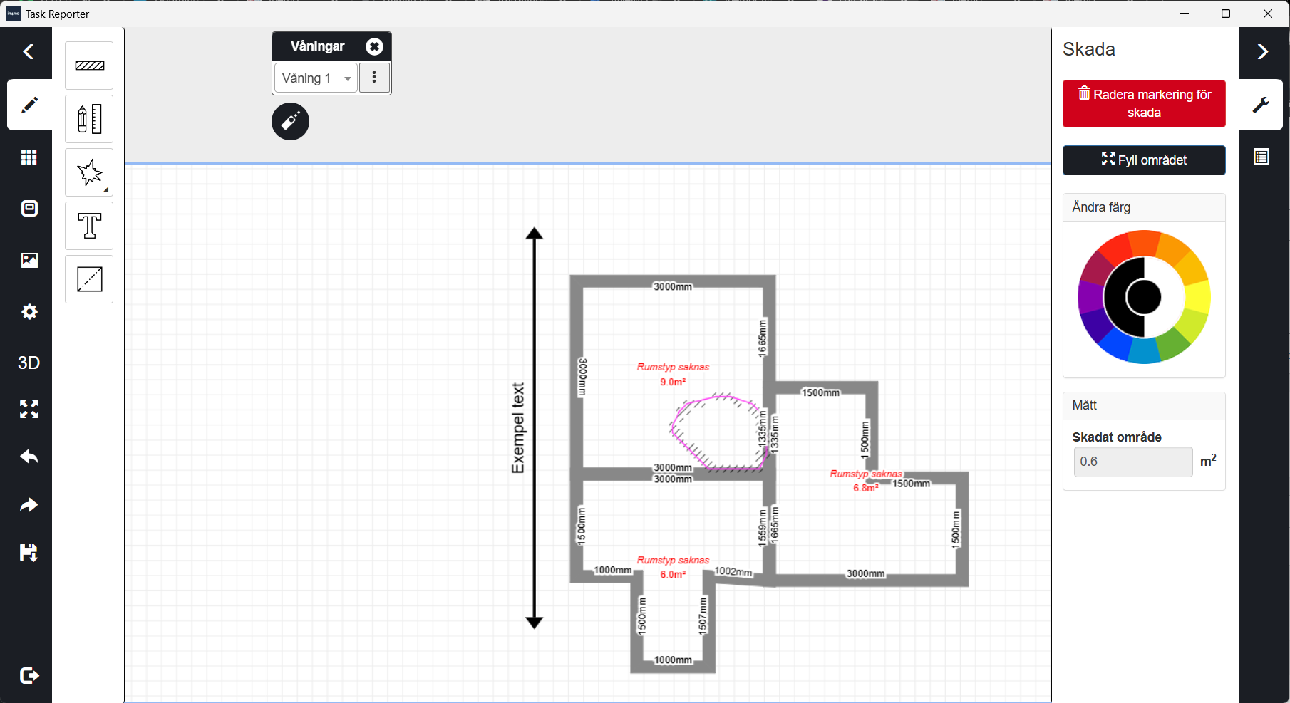
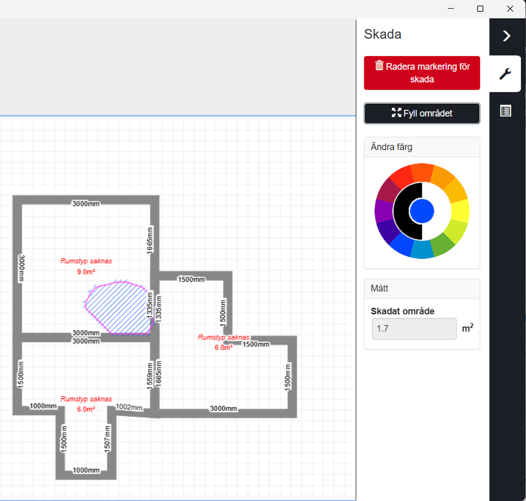
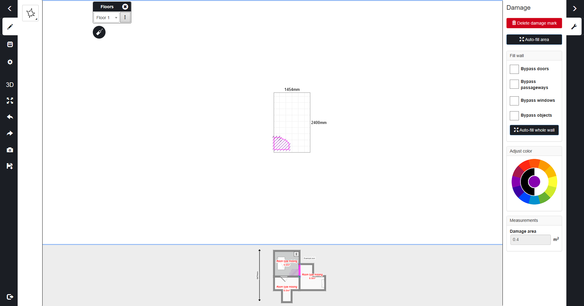
Skadeytans storlek visas till höger. Denna storlek kan användas i kostnadsberäkningar för iCC-ärenden. Genom att trycka på Fyll i område automatiskt fylls det ritade skadeområdet, och den totala storleken för området visas.
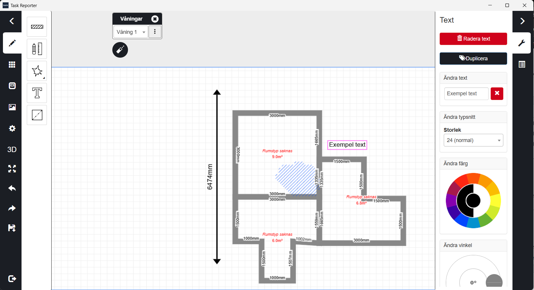
Den fjärde ikonen låter dig lägga till text i bilden för att förklara planritningen bättre. Textens storlek, färg och vinkel kan ändras i menyn till höger.

Den sista ikonen låter dig lägga till objekt i planritningen. Dessa objekt kan subtraheras från golv- eller väggytan. Det kan till exempel vara en köksö som finns i köket men inte på samma golvnivå som resten av köket – då kan du lägga till ett objekt som representerar köksön.
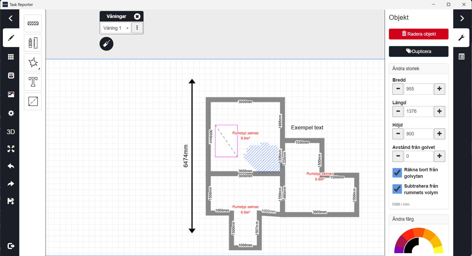
För att lägga till ett objekt väljer man den femte ikonen och ritar sedan objektet i planritningen där man önskar placera det. Man kan ändra storlek, färg och vinkel på höger sida. Om Subtrahera från golvyta är markerat kommer den yta som täcks av objektet inte att räknas med i rummets golvyta.
Objekt kan flyttas genom att trycka på dem och dra dem till önskad plats. Genom att snabbt trycka på objektet växlar man mellan rummet och objektet.
Om objektet även påverkar väggytan måste det placeras så att det vidrör den eller de väggar som påverkas.
För att subtrahera objektets yta från väggytan trycker man på väggen, går till det grå området högst upp på sidan, trycker sedan på objektet och markerar rutan Subtrahera från väggyta. Observera att om ett objekt flyttas så att det inte längre är anslutet till golvet kommer det inte längre att subtraheras från golvytan.

Under den tredje ikonen finns de färdiga rumstyperna, som visas i början av dessa instruktioner. Rum läggs till i planritningen genom att trycka på önskat rum och dra det till det vita området. Måtten kan ändras både före och efter att rummet har lagts till om det behövs.

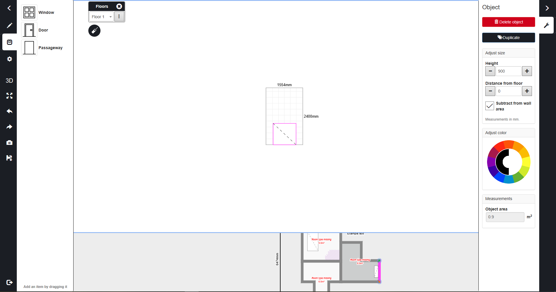
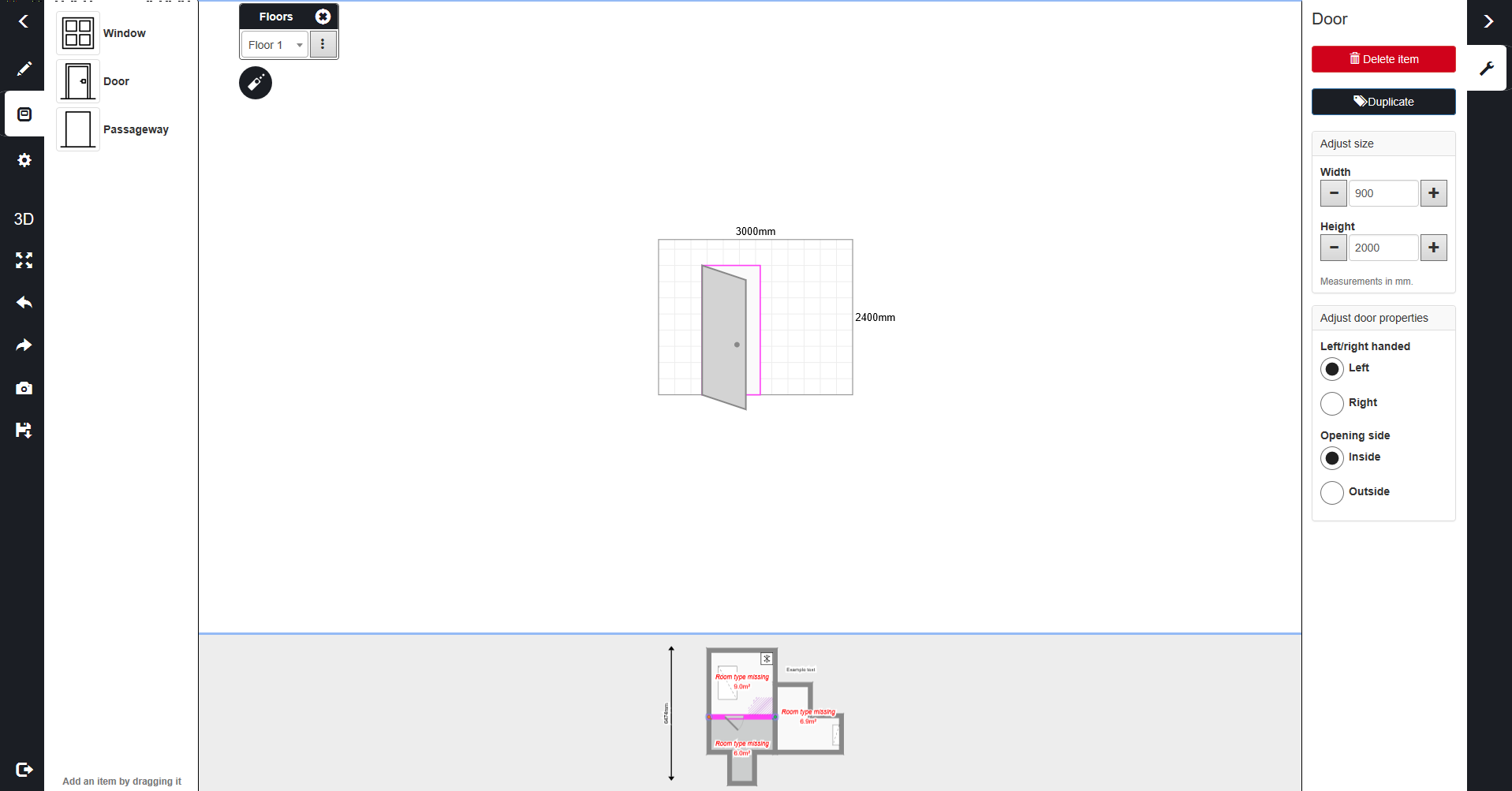
Under den fjärde ikonen kan fönster, dörrar och genomgångar läggas till direkt på väggarna. Välj den dörr/fönster du behöver och dra den till den vägg där den ska placeras. På höger sida kan du ändra dörrens/fönstrets mått.

Under den femte ikonen finns clipart-ikoner som kan läggas till i planritningen för att representera hushållsartiklar och detaljer i lägenheten/huset. Storleken och vinkeln på objekten kan ändras, liksom avståndet från golvet, och det är möjligt att dra av objektens yta från rummets eller golvets yta. Clipart-bilder visas även i FloorPlanner 3D-vyn.

Dörrar, fönster och öppningar kan också läggas till i planritningen genom att klicka på den vägg där du vill lägga till dörr(ar)/fönster.

När du har klickat på väggen, klicka på det grå området som visas högst upp i planritningen eller lägg till direkt i planritningen.
När man klickar på det grå området visas den valda väggen mer i detalj.
Man kan lägga till skador på väggarna genom att klicka på pennikonen. Därefter ritar man på väggen där skadan finns.

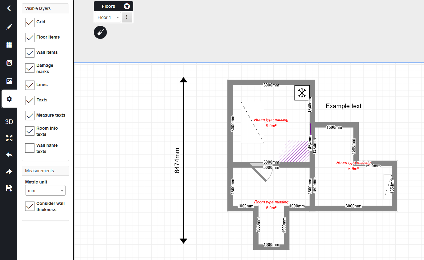
I inställningarna kan man välja vilka element man vill ska vara synliga i planritningen. Om man till exempel vill ha planritningen i besiktningsrapporten utan skademarkeringar och mätningstexter, avmarkera dessa lager. De dolda lagren sparas fortfarande i planritningen, men visas inte i rapporten.
Dessutom kan man ändra enhet och tröskelvärde för redigering i inställningarna.

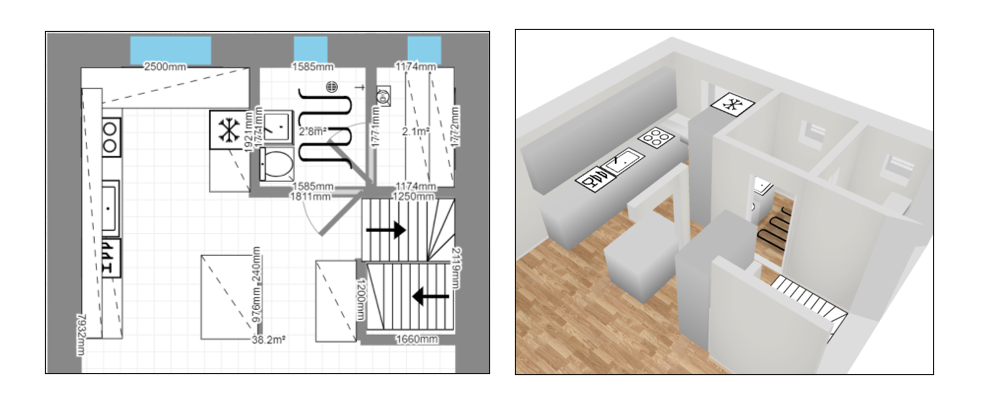
3D-knappen gör det möjligt att visa planritningen i 3D. I denna vy visar verktyget det skadade området samt eventuella objekt och clipart som har lagts till i ritningen. Tillsammans med möjligheten att ta ögonblicksbilder av 3D-vyn går det att ta informativa bilder som till exempel kan läggas till i rapporter. För att återgå till den vanliga vyn, tryck på 2D-knappen.


Den här knappen centrerar planritningen igen och anpassar storleken så att den passar på skärmen.

Genom att klicka på ångra-knappen ångrar man den senaste ändringen.

Genom att klicka på gör om-knappen återställer man det senaste som togs bort med ångra-knappen.

Sparar planritningen.

Avslutar in4mo FloorPlanner. När man klickar på denna knapp kommer systemet att fråga om man önskar spara planritningen innan man avslutar.
Det är möjligt att kopiera planritningen som skapats i FloorPlanner till de tomma bildfälten i rapportssektionen Bilder från platsen.

Man bör dock vara försiktig när man gör detta, eftersom systemet endast sparar en version av planritningen. Om man alltså redigerar planritningen under bildsektionen och sparar den, och senare vill ändra den ursprungliga planritningen som visas i sektionen Planritning, kommer man att få den senast sparade versionen av planritningen, vilket inte nödvändigtvis är den ursprungliga planritningen som man just klickade för att ändra. Om man inte redigerar tidigare versioner av planritningen kommer systemet att behålla en bild av dem i rapporten. Därför bör det kontrolleras att planritningen i sektionen Planritning inte behöver några ändringar innan man kopierar den.
Ytterligare väggfunktioner
Det finns olika funktioner i FloorPlanner som gör det möjligt för användare att anpassa väggarna efter varje väggs specifika behov.
(Inrednings) väggar som inte börjar vid golvet
Ibland finns det väggar i byggnader som inte sträcker sig från taket hela vägen ner till golvet. Detta kan bero på strukturella skäl eller på att rör och/eller ledningar är inbyggda i taket. För att kunna lägga till sådana väggar i planritningarna finns en parameter Avstånd från golv i väggmenyn.
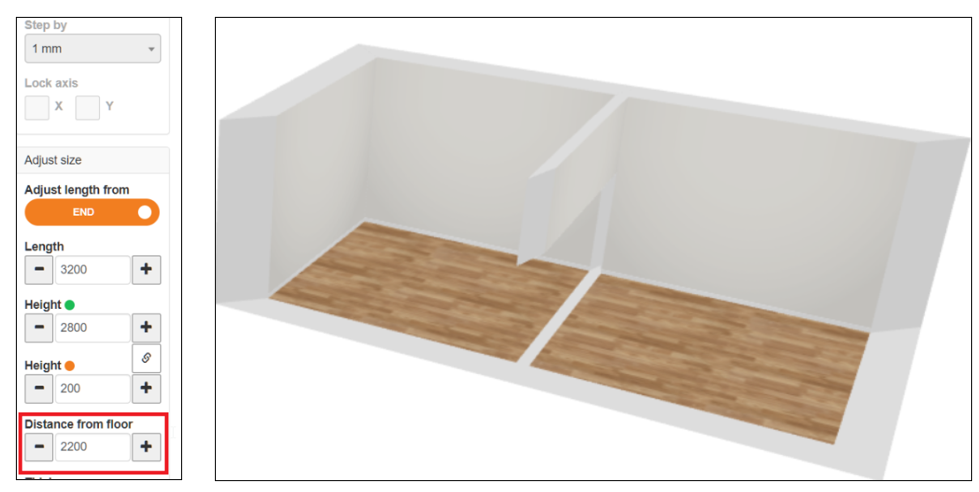
Ofta delar dessa mindre väggliknande element inte upp ett utrymme i separata rum, och i sådana fall bör de läggas till i planritningen som inredningsväggar.
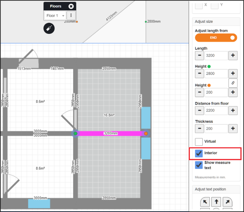
Dessa inredningsväggar är riktiga väggliknande strukturer som inte delar upp ytan i separata rum och får inte blandas ihop med den redan befintliga funktionen som kallas virtuella väggar. Virtuella väggar är inte riktiga väggar eller väggliknande, men delar ändå upp ytan i två rum. Virtuella väggar används t.ex. för att separera ett öppet kök från vardagsrummet som finns i samma yta.
En vägg kan definieras som en inre vägg genom att markera kryssrutan inredningsvägg i väggmenyn. Observera att denna kryssruta endast är tillgänglig för väggar som inte börjar från golvet. Observera också att en vägg inte kan vara både virtuell och inredningsvägg, så båda kryssrutorna kan inte markeras samtidigt.
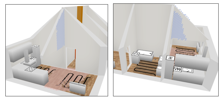
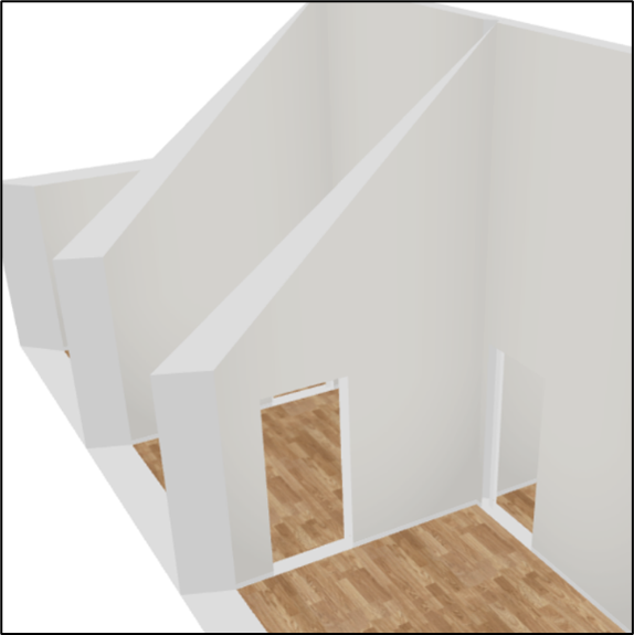
Snedtak
I rum med snedtak vill man kunna definiera olika vägghöjder för olika väggar i rummet. Detta är möjligt genom att ange två höjder för taket eller väggen, vilket görs enkelt med hjälp av de olika färger som tilldelats väggarnas två ändar.
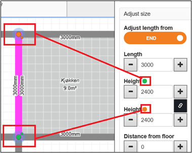
Snedtaket beaktas i de väggmått som FloorPlanner räknar ut automatiskt och kan även ses i 3D-vyn.
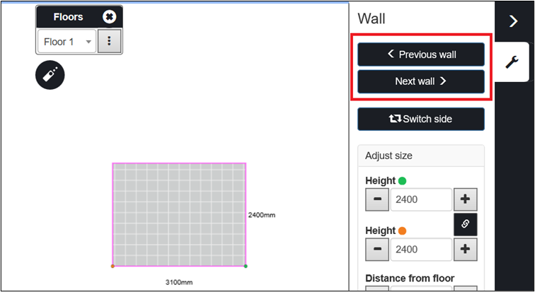
Enkel navigering mellan väggar
I väggvyn kan man enkelt navigera till andra väggar i samma rum genom att använda navigeringsknapparna. Detta eliminerar behovet av att gå till golvvyn för att välja en annan vägg att arbeta med.
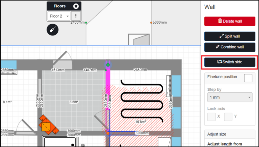
I golvvyn kan man också byta sida på en inredningsvägg genom att använda knappen Byt sida.
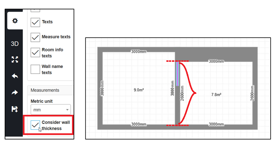
Väggtjocklek
När användaren har aktiverat inställningen för väggtjocklek kommer FloorPlanner att ta hänsyn till måtten på båda sidor av en vägg, och tillåter endast att fönster, dörrar och öppningar placeras inom det område som delas av båda sidor av väggen.
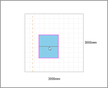
I väggvyn visas ramen inom vilken objektet kan placeras med en streckad linje, vilket indikerar att måtten på andra sidan väggen är olika och därför påverkar var objektet kan placeras.
För mer detaljerad information om hur funktionen för väggtjocklek fungerar, se våra instruktioner för FloorPlanner Väggtjocklek och Finjustering: The FloorPlanner Wall Thickness Feature and Finetuning Tool.
Finjusteringsverktyg
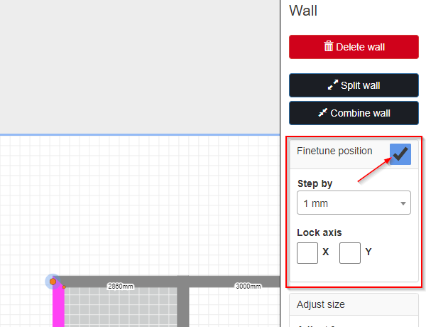
Finjusteringsverktyget ger extra kontroll över väggarna och hörnen i planritningen.
Man kan använda finjusteringsverktyget i båda lägena Ta hänsyn till/ignorera väggtjocklek genom att markera kryssrutan Finjustera position i menyraden till höger när en vägg är vald.
Funktionen gör det möjligt att dra väggar och vägghörn med precision enligt vald enhet. Som standard är stegen 1 mm, men detta kan ändras till 1 cm (10 mm) eller 10 cm (100 mm) genom att välja dessa alternativ i rullistan Steg för steg.
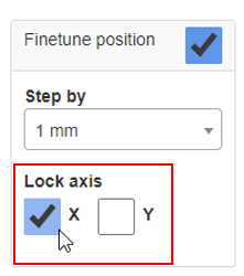
Som standard kan man dra fritt både vertikalt och horisontellt. Man kan dock begränsa detta ytterligare genom att låsa axelriktningarna:
-
Markera kryssrutan X för att låsa horisontell dragning; väggarna kan då endast flyttas upp eller ner.
-
Markera kryssrutan Y för att låsa vertikal dragning; väggarna kan då endast flyttas åt sidan.
- Observera att man endast kan låsa en axelriktning åt gången.

Lägg till flera våningar i planritningen
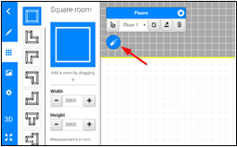
Verktyget gör det möjligt att skapa en planritning med upp till tio våningar. Våningen man börjar med kallas som standard Våning 1, och vågningsmenyn visas ovanför ritfältet.

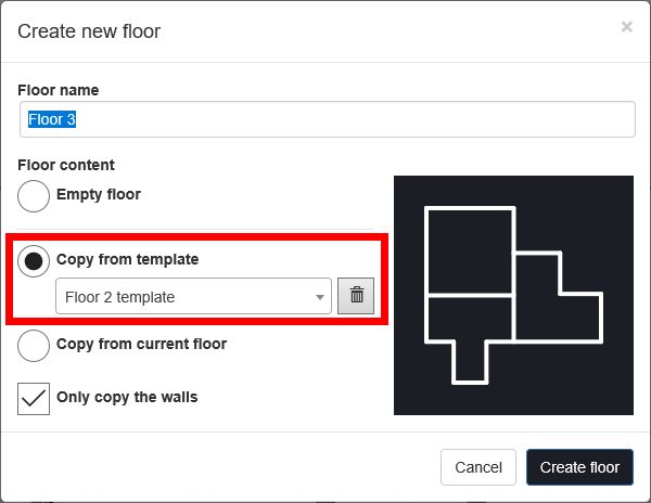
För att lägga till fler våningar, klickar man på ![]() , vilket öppnar ett fönster där man kan namnge den nya våningen och välja vilken våning man vill skapa.
, vilket öppnar ett fönster där man kan namnge den nya våningen och välja vilken våning man vill skapa.
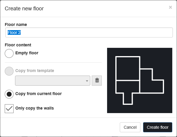
Om man väljer Tom våning öppnas en tom sida och man kan börja från början. Om man väljer Kopiera från aktuell våning får man möjlighet att välja en mall som man tidigare har sparat (golv-/våningsmallar beskrivs närmare senare). Genom att välja Kopiera från aktuell våning kopieras den nya våningen från den våning man visar när man lägger till den nya våningen. Om man inte vill att den nya våningen ska ta med något annat innehåll från aktuell våning eller mall kan man markera rutan Kopiera endast väggar. En förhandsvisning av den nya våningen visas i rutan till höger.
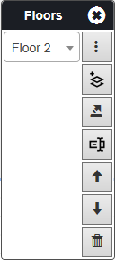
När man har lagt till flera våningar kan man byta mellan dem i vågningsmenyn genom att välja våning i rullgardinsmenyn.
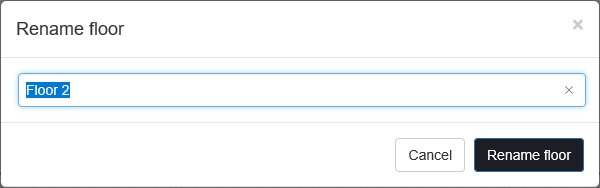
Knappen ![]() gör det möjligt att ändra våningens namn. Våningarna får automatiskt namn som Våning 1, Våning 2 och så vidare, men man kan ändra detta om man vill.
gör det möjligt att ändra våningens namn. Våningarna får automatiskt namn som Våning 1, Våning 2 och så vidare, men man kan ändra detta om man vill.

Knappen ![]() gör det möjligt att spara våningen som en mall. Våningsmallar kan senare användas i andra ärenden, på samma enhet och konto. Detta kan vara användbart om man arbetar med flera lägenheter med samma planlösning.
gör det möjligt att spara våningen som en mall. Våningsmallar kan senare användas i andra ärenden, på samma enhet och konto. Detta kan vara användbart om man arbetar med flera lägenheter med samma planlösning.
Som standard får mallarna namnet på våningen plus ett nummer; Våning 1-mall, Våning 2-mall och så vidare, men man kan ändra namnet om man vill. Det är en bra idé att ge dem namn som gör dem lätta att känna igen senare.
Kortkommandon och tangentbordsfunktioner
När ett tangentbord är tillgängligt finns flera användbara kortkommandon och tangentbordsfunktioner som kan användas, vilket gör det snabbare och enklare att arbeta i FloorPlanner.
- ÅNGRA: Ctrl + Z
- GÖR OM: Ctrl + Shift + Z eller Ctrl + Y
- SPARA: Ctrl + S
Olika objekt i planritningen kan också flyttas med piltangenterna på tangentbordet:
- I golvvyn: Använd piltangenterna för att flytta objekt, clipart, texter, linjer, skador och väggar.
- I väggvyn: Använd piltangenterna för att flytta dörrar, öppningar, fönster, objekt och skadade områden.
Hilti- och Leica-mätinstrument i in4mo Task Reporter
I in4mo Task Reporter är det också möjligt att ansluta både ett Leica (Disto-serien) och ett Hilti (PD-I) avståndsmätinstrument och använda de uppmätta värdena direkt i in4mo FloorPlanner-verktyget eller i arbetsplanen.
För att ansluta ett mätinstrument, aktivera Bluetooth på både surfplatta och instrument. Klicka på mätinstrumentikonen i in4mo FloorPlanner och välj enheten från listan för att ansluta.
Välj fältet där du vill mata in värden, till exempel rummets bredd. Mät sedan med mätinstrumentet. Det uppmätta värdet fylls nu automatiskt i fältet.
Alternativt kan du göra flera mätningar med mätinstrumentet, och när du sedan väljer ett inmatningsfält i in4mo FloorPlanner visas de senaste mätvärdena i listan och kan väljas.
Mätningarna kan också användas när du ritar väggar för hand. Det senaste mätvärdet används när väggen ritas, vilket gör det möjligt att mäta och skriva utan att behöva ange specifika värden.
Det går även att ansluta mätinstrumentet och använda mätvärdena när du fyller i värden i arbetsplanen. Mätvärdena kan endast användas för arbetsobjekt med motsvarande enheter i in4mo och mätinstrumentet.
Använd mätningar från in4mo FloorPlanner i arbetsplanen (iCC)
De mätningar man lägger till i planritningen kan användas i arbetsplanen i in4mo Cost Calculation (iCC). Eftersom det är möjligt att lägga till dörrar och fönster i verktyget kan både brutto- och nettoväggyta beräknas.
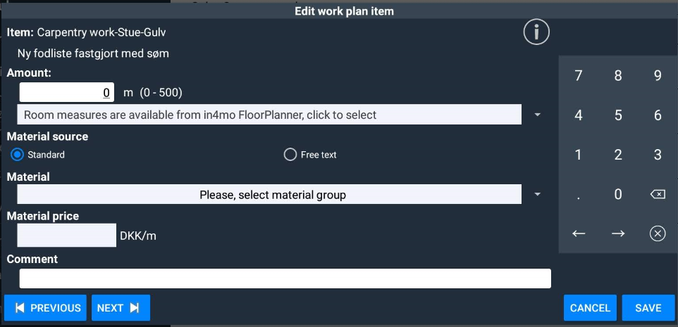
När en arbetspost läggs till i en arbetsplan på ett ärende där det finns en planritning med mätningar, skapad i in4mo FloorPlanner, blir det möjligt att använda dessa mätningar för arbetsposten.
När en arbetsplan skapas och mätningar ska läggas till för arbetsposten, är det möjligt att använda de mätningar som lagts till i in4mo FloorPlanner. Om man väljer att använda mätningarna från planritningen importeras dessa till arbetsposten och även till andra objekt med samma enhet i rummet och strukturen.
iCC i FloorPlanner
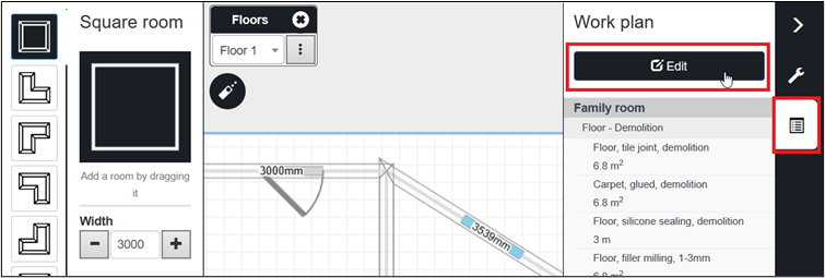
När ett ärende/uppdrag innehåller iCC-arbetspost, kommer användare med behörighet att se dem att ha en flik Arbetsplan i högermeny i FloorPlanner-verktyget, vilket kan ge en översikt över de kostnader som är involverade.
Arbetsplanen visar arbetsposten i det valda rummet, eller om inget rum är valt visas alla arbetsposter i ärendet/uppdraget. Om ett objekt eller en struktur är valt visas arbetsposten i det rum som objektet eller strukturen tillhör (förutsatt att rummet är ett iCC-rum).
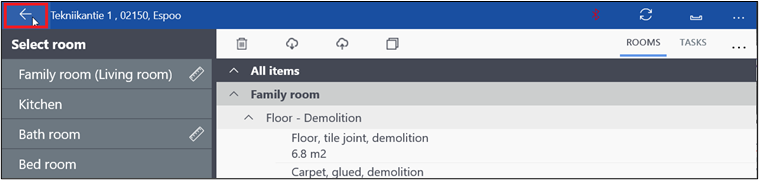
Det är möjligt att navigera direkt mellan FloorPlanner och arbetsplanen genom att klicka på knappen Redigera på fliken Arbetsplan. Detta ger en fråga om att spara alla ändringar som gjorts i ritningen, och när valet har gjorts öppnas arbetsplansvyn. Efter att nödvändiga ändringar eller tillägg gjorts i arbetsplanen kan man återgå till planritningen genom att klicka på tillbaka-knappen, och ändringarna kommer att återspeglas i ritningen.